HSX BLOG
How to Estimate Die Cast Motor Housing Costs
Is One Drawing Enough Customers often ask whether a single 3D model is enough for a die cast motor housing quotation. It may be enough for a preliminary estimate, but it is rarely enough for a production-ready quotation.
Is One Drawing Enough
Customers often ask whether a single 3D model is enough for a die cast motor housing quotation. It may be enough for a preliminary estimate, but it is rarely enough for a production-ready quotation.
A 3D model can show the overall size, geometry and approximate material volume. It usually does not define every critical tolerance, machining operation, finish, order quantity or acceptance requirement. When those details are missing, the estimate must rely on clearly stated assumptions.
The part price also depends on more than casting weight and aluminum cost. Tooling, casting difficulty, secondary operations, inspection, packing and expected volume can all change the quotation. The following review sequence explains what one drawing can support and what additional information improves quote accuracy.
1 What a 3D Model Can Support
If the model includes the complete internal cavity, ribs, bosses, holes and slots, a supplier can usually make an initial assessment of the casting and establish assumptions for several cost items.
Maximum part envelope and an approximate mold size
Main wall sections, local heavy areas and possible filling difficulties
Likely parting direction, slide requirements and ejection risks
Approximate casting volume, theoretical weight and material cost range
Functional areas that may need machining allowance
A 3D model normally does not replace a controlled 2D drawing. Without dimensional tolerances, geometric requirements and technical notes, the supplier cannot reliably determine machining time, fixture requirements, inspection methods or quality cost. A quotation based only on a 3D model should therefore be identified as a preliminary estimate, with its assumptions and exclusions listed.
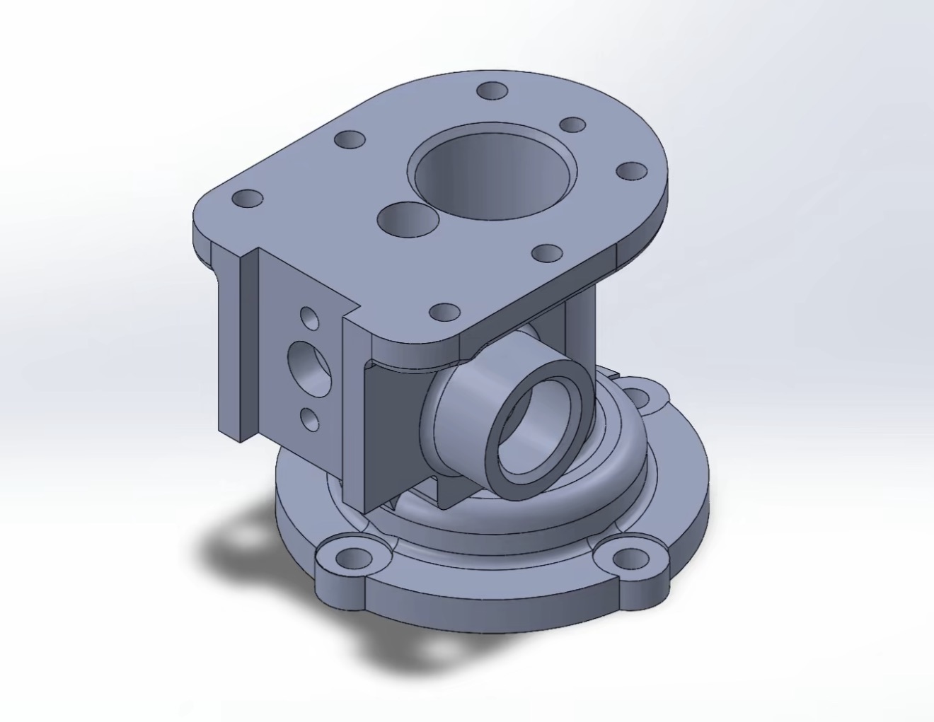
3D model example. Shows geometry, cavities, ribs, bosses and holes.
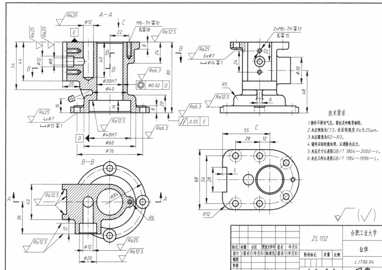
2D drawing example. Defines dimensions, tolerances, datums and requirements.
These files show the same reference component and illustrate the different role of each file. They are not presented as the motor housing discussed in this article.
2 Casting Structure and Tooling Cost
The first structural review considers whether the part can be cast consistently. Maximum dimensions, wall transitions, deep cavities, side features and the number of core pulls can affect mold construction, machine selection, production cycle and trial risk.
Provide the overall length, width and height, together with the main external envelope
Show the main wall sections and identify areas with large thickness changes. A relatively consistent wall distribution generally supports more predictable filling, but the acceptable range depends on the alloy, part size, flow distance and local geometry
Include ribs, bosses, holes, slots and internal cavities instead of submitting an oversimplified model
If a preferred die opening direction or parting location already exists, mark it for mold review
A complex structure is not automatically unsuitable for die casting. It may, however, require additional slides, inserts or core actions and may increase mold maintenance and process control requirements. The quotation should state whether these features are included in the proposed tooling concept.
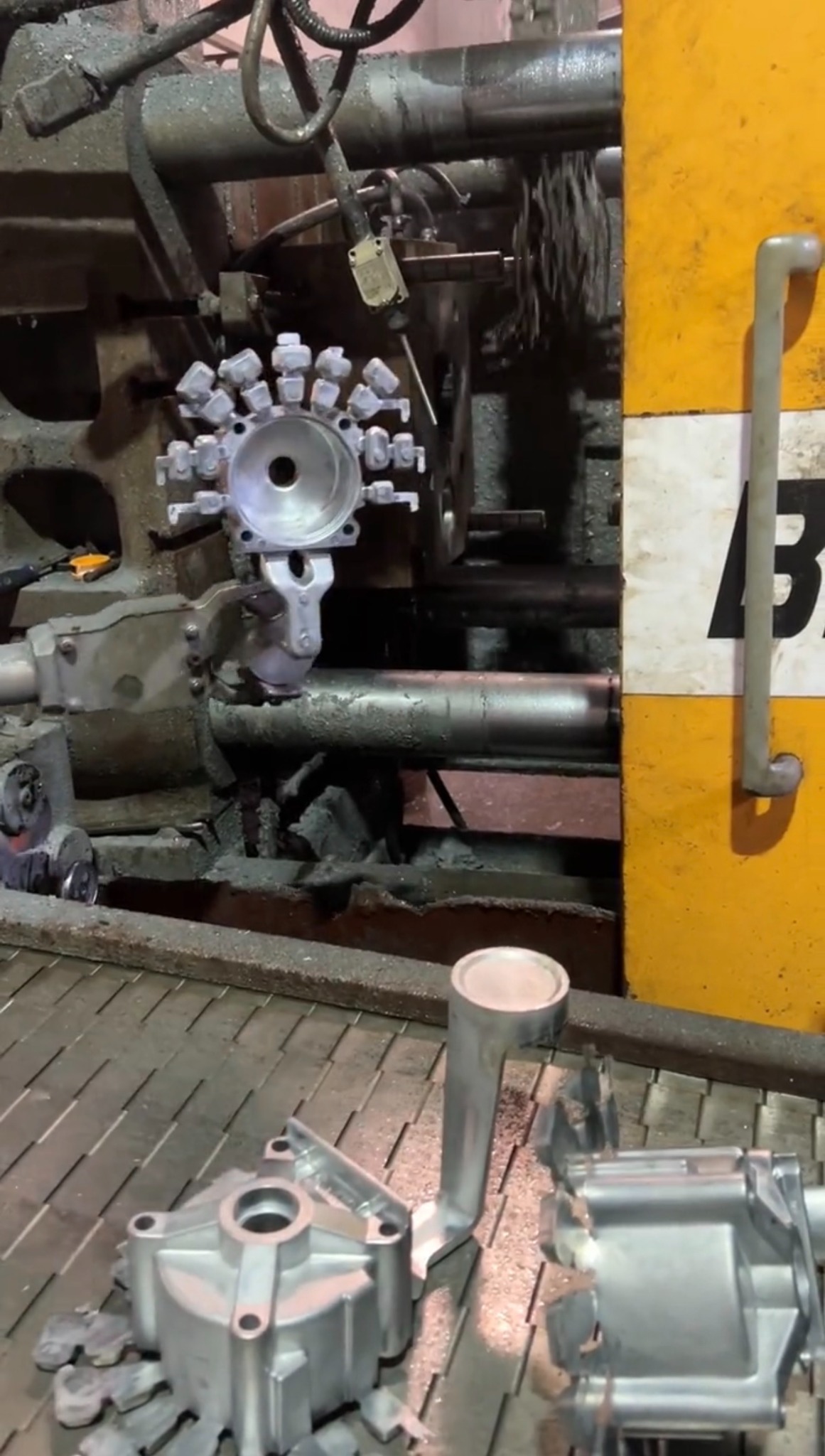
Die casting production example. Part geometry and mold design affect machine selection and cycle planning.
3 Critical Interfaces Tolerances and Inspection
A motor housing does not need the same accuracy on every surface. Depending on the product, bearing bores, the stator fit, locating features, mounting faces and sealing surfaces may have a greater effect on assembly than nonfunctional cast surfaces. The drawing should distinguish these interfaces from general casting dimensions.
Bearing bore diameter, depth, shoulder, chamfer and positional relationship where applicable
Stator fit diameter, effective engagement length and any required roundness or cylindricity
Locating diameter, depth, face and assembly direction for mating covers or components
Required concentricity, runout or perpendicular relationship between controlled bores, locating features and faces
Mounting surface flatness and the positional requirements of mounting holes or counterbores
The drawing should also distinguish as-cast dimensions from finished dimensions. A tighter tolerance may require more than extra machining time. It can also require another setup, a dedicated gauge, additional in-process checks or full inspection. The functional requirement should be clear before those costs are added.
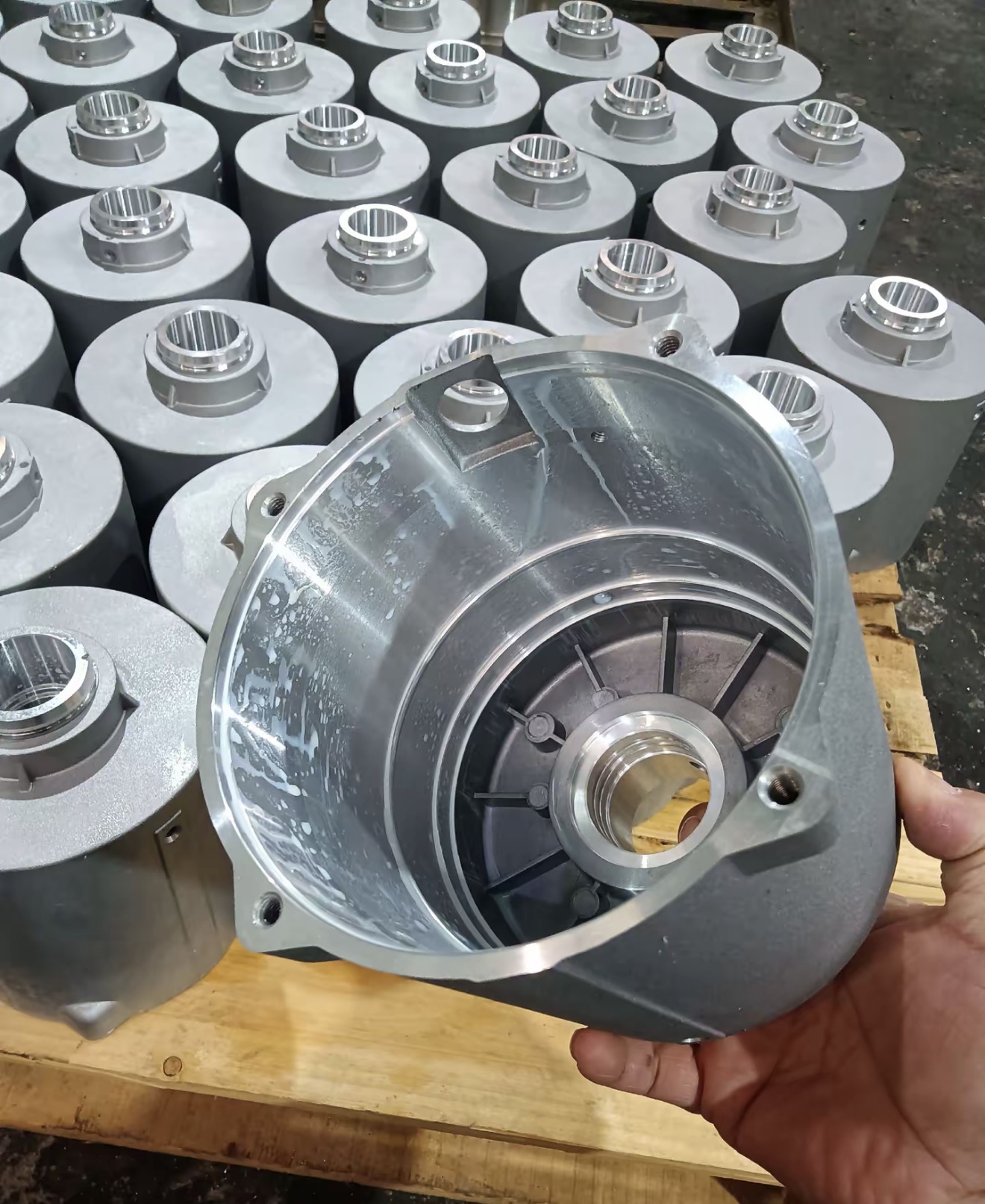
Machined interface example. Define bore size, datums, tolerances and inspection requirements on the drawing.
4 Machining Scope and Method
Machining cost cannot be estimated from the number of holes alone. The quotation depends on which features require machining, how the part will be located, whether it must be turned over, whether tools can reach each feature and how the finished dimensions will be checked.
Confirm whether bearing bores, the stator fit, locating diameters, flange faces, mounting faces or sealing surfaces require machining
List every drilled hole, tapped hole, counterbore and thread with its size, quantity and effective depth
Identify the design and inspection datums. Machining datums must be confirmed against the part function and fixture concept rather than applied uniformly to every housing
State whether critical dimensions will be sampled or checked on every part, and whether gauges, dimensional reports or capability records are required
HSX can confirm the scope of in-house drilling, tapping and other listed secondary operations during project review. CNC machining is coordinated through partner resources when the drawing requires it. A formal quotation should separate the casting, in-house secondary operations, partner machining and inspection scope.
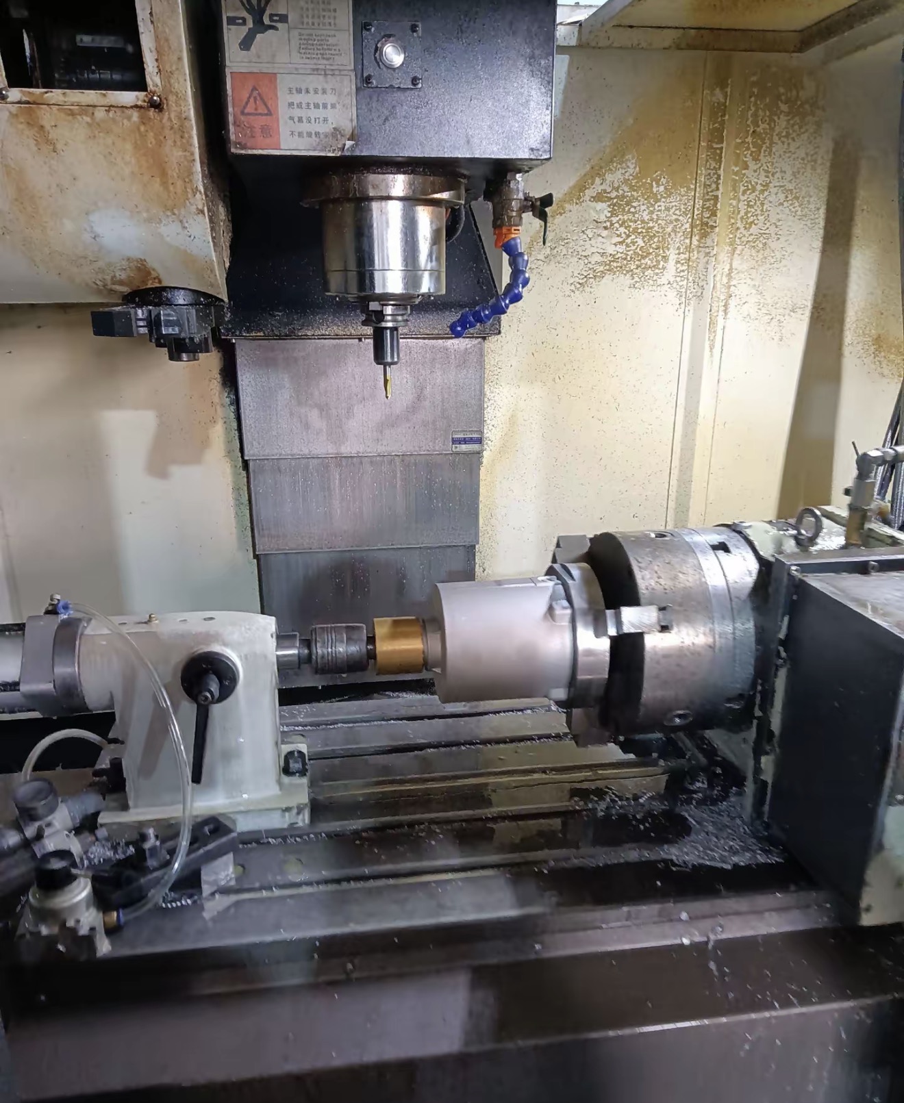
Machining operation example. Bores, locating features and mounting faces may require machining after casting.
5 Alloy and Surface Requirements
If the alloy and its governing specification are already defined, include them on the drawing. ADC12 and A380 are both used in aluminum die casting projects, but they should not be treated as directly interchangeable without confirming the required properties, specification and customer approval. If the alloy is still open, provide the mechanical, corrosion, appearance, machining and service requirements for review.
State the alloy designation and applicable customer or project specification instead of writing only aluminum alloy
Define the finish, color, appearance zones and acceptable surface conditions
For salt spray or other corrosion requirements, provide the test method, conditions, duration and acceptance criteria that apply to the product
If anodizing, electrophoretic coating or plating is required, first confirm whether the selected die casting alloy, surface condition and appearance target are compatible
HSX performs die casting, trimming, deburring, gate removal, drilling, tapping, polishing, powder coating, spray painting, quality inspection and packing in-house. Anodizing, electroplating and selected additional processes are coordinated through partner resources and confirmed for each project.
6 Volume Delivery and Tooling Assumptions
The same drawing can lead to different tooling and cost assumptions at different quantities and project stages. Provide the prototype quantity, first production quantity, estimated annual demand, expected project life and target delivery rhythm whenever possible.
Prototype quantity and whether machining, finishing and a dimensional report are included
First production quantity and estimated annual demand
Expected project life, tooling life requirement and spare tooling plan
Target timing for samples and production, together with any fixed approval milestones
Volume can affect cavity planning, tooling investment, production scheduling and the allocation of cost per part. It does not by itself determine one mold concept. The supplier must also consider the part size, geometry, quality requirements and project life. Delivery timing should be evaluated by stage, including drawing confirmation, tooling, trial runs, sample approval and production preparation.
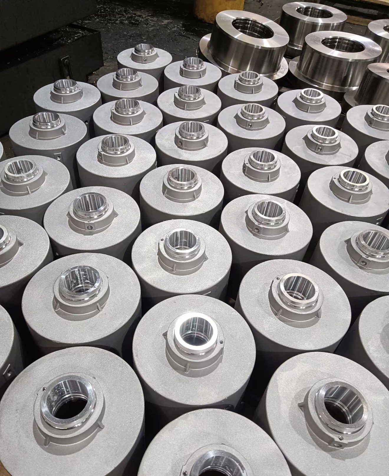
Batch production example. Expected volume and project life affect tooling, scheduling and cost allocation.
7 Quality Packing and Quotation Boundaries
Some costs do not appear in the 3D model but still affect the formal quotation. Appearance, sealing, inspection, documentation and packing requirements should be identified early.
Define appearance zones and the acceptance limits for flow marks, ejector marks, burrs, color variation and other visible conditions
If the product requires protection against water, dust or oil, provide the complete product target, sealing concept and validation conditions. A single cast housing cannot independently establish the performance of the assembled product
State whether leak testing, pressure testing, full inspection of critical dimensions, material documentation or dimensional reports are required
Define packing, individual protection, labels, traceability and commercial terms that form part of the quotation
Each requirement should correspond to a defined process or acceptance condition. This makes competing quotations easier to compare and reduces the risk of additional costs appearing after the project begins.
Minimum Information for a Preliminary Estimate
3D or 2D data. Complete model or drawing showing the main dimensions and internal structure
Critical functions. Applicable bearing bores, stator fit, locating features, mounting faces and sealing surfaces
Machining scope. Faces, bores, holes, threads and known tolerances
Alloy and finish. Specified alloy or performance requirements and the required surface condition or finish
Volume plan. Prototype and first production quantities, annual demand and project life
Quality requirements. Appearance, sealing, inspection, documentation and packing
If some information is not yet available, send the current files and identify the open items. The preliminary estimate should state its assumptions, exclusions and the conditions that could change the price. Before a formal quotation is finalized, both parties should confirm the controlled drawing, technical requirements, quantity and supply scope.
When One Drawing Is Not Enough
A 3D model can support an early geometry review and approximate cost range. A controlled 2D drawing is normally required for tooling quotation, sample development and production approval because it defines tolerances, datums, material and technical requirements.
If only a physical sample is available, state its source, required changes, application and expected quantity. HSX will confirm whether measurement or reverse engineering is required; the customer covers sample shipping.
Send Your Files for Project Review
For a motor housing inquiry, send a STEP or STP model, controlled 2D drawing, critical interfaces, machining scope, alloy and finish, quantity and application. Mark any open items. HSX will confirm casting feasibility, quotation assumptions, in-house operations and any partner-supported machining or finishing required by the drawing.
Related information Projects | Machining Guide | Send Drawing
Continue reading
Convert general guidance into a project-specific review.
Share a drawing, 3D file, sample or requirement so HSX can review the actual geometry, process route and finishing boundary.