HSX BLOG
Custom Aluminum Die Cast Brackets from Drawing to Delivery
Custom aluminum die-cast brackets move from drawing review to tooling, casting, finishing and inspection before shipment. This guide explains the technical details and delivery requirements buyers should confirm to obtain an accurate quotation and reduce avoidable production changes.
Aluminum die cast brackets can support equipment, connect components and provide mounting points. A custom project typically involves drawing review, tooling, die casting, secondary operations, inspection and packing. Defining the part’s function, delivery condition and acceptance requirements gives the supplier a basis for assessing the manufacturing route, quotation and schedule.
Using bracket components as an example, this guide explains how HSX reviews customer drawings, samples and project requirements, and what buyers need to confirm at each stage.
Quick answer
Supply scope: Decide whether you need trimmed castings or components with machining and surface finishing completed.
Critical requirements: Identify the dimensions, assembly interfaces and appearance criteria that must be defined on the drawing or in acceptance documents.
Quotation inputs: Provide the alloy, quantities, secondary operations, inspection and packing requirements together wherever possible.
1 Confirm the part requirements
For a custom bracket project, we first review the application, geometry and delivery requirements, then define the manufacturing scope behind the quotation. Complete information makes it easier to align the proposed route and price with the part you need.
Part function and application
Component type: Identify whether the part is a U-shaped mounting bracket, L-shaped connector, support base or equipment mounting component. Include its overall dimensions, structural features and relationship to other parts.
Operating environment: Explain whether the component is installed inside equipment, used outdoors or exposed to moisture, corrosive substances or elevated temperatures. These conditions affect the alloy, finish and acceptance requirements.
Assembly: Provide mating parts or an assembly view showing fastening, locating and contact areas. State any load, vibration or welding requirements and the associated verification conditions so that material and process suitability can be assessed.
Drawings and delivery requirements
Drawings or samples: A STEP or STP model is recommended, together with a 2D drawing defining dimensions, tolerances, threads and surface requirements. If only a physical sample is available, agree the measurement scope, critical features and permitted changes before establishing the production reference.
Material: Specify the alloy grade and applicable standard on the drawing. Evaluate ADC12, A380 and other die casting alloys against casting requirements, mechanical properties, operating conditions and finishing needs. Any substitution requires customer approval.
Quantities: Separate the sample quantity, first production order, repeat order frequency and estimated annual demand. These inputs support tooling decisions, scheduling and part pricing.
Finish and delivery condition: Confirm whether you need the trimmed as-cast surface or additional polishing, powder coating, spray painting or another finish. Identify cosmetic surfaces, mating faces and masking areas. Acceptance of ejector marks or flow marks depends on their location and the agreed criteria.
2 Review manufacturability before tooling
Drawing review establishes whether the part can be manufactured as specified and which requirements affect tooling, casting, secondary operations and cost. Any drawing changes are agreed with the customer before tooling is made to the revised design.
Geometry and casting conditions
Part size and equipment suitability: Assess projected area, expected cavity pressure, die dimensions, shot requirements and machine capability when selecting the equipment and number of cavities. Part weight is one input to this review.
Wall thickness and local heavy sections: Review changes in wall thickness, thick junctions and thin sections for filling, shrinkage and distortion risks. Achievable wall thickness depends on the alloy, flow distance and overall geometry.
Holes and ribs: Determine which holes can be cast, which need machining and whether side holes require core pulls. Ribs, mounting bosses and the material around holes must also accommodate filling, ejection and assembly.
Parting and release: Review the die opening direction, parting line, draft and side features. Coordinate gate, ejector and trimming locations with critical assembly surfaces and appearance requirements.
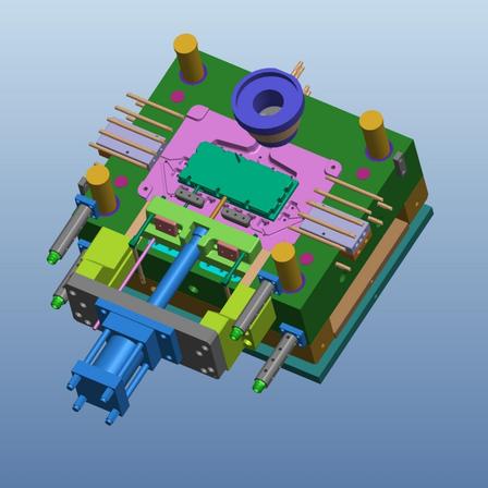
Tooling proposal and trial castings
The tooling proposal considers gating, venting, overflows, ejection and any required core pulls. If abrupt wall changes, deep-hole release conditions or restricted machining access create manufacturing concerns, we explain the effect and discuss feasible changes with the customer.
After tooling is completed, trial castings are used to review filling, release, dimensions and compatibility with later operations. Adjustments follow the trial results. Samples also need to be assessed against the agreed machining, finishing and inspection requirements before they become the reference for production.
3 Plan secondary operations around the delivery scope
After die casting, the part needs the required gate removal, deburring and other trimming operations. Drilling, tapping, precision machining and surface finishing depend on the delivery scope. Castings that have completed the agreed trimming and inspection can also be the finished deliverable for an order.
Gate removal and deburring
Gate removal separates gates, runners and overflows from the casting and dresses the remaining attachment areas. Press trimming, cutting or other methods are selected around the geometry, access and surface requirements.
Deburring removes flash, burrs and sharp edges at parting lines, holes and other boundaries to meet the agreed handling, assembly and appearance requirements. Any subsequent polishing or sandblasting should be included in the process review.
Drilling and tapping
Choose the manufacturing method for mounting holes, locating holes and threaded holes according to their function, size and position requirements. Holes that require machining need suitable datums, workholding and tool access.
Hole size, surface quality and location require separate control. Reaming primarily improves the size and surface quality of an existing hole; it should not be relied on to correct a misplaced hole. Tight positional requirements need to be addressed in the locating and machining plan.
For internal threads, specify the thread size, effective depth, through-hole or blind-hole form, and any masking needed during coating. HSX performs drilling and tapping in-house.
Precision machining and surface finishing
Mounting faces, locating registers or mating bores with tighter requirements may need milling, boring, turning or another suitable finishing operation. HSX coordinates CNC machining and CNC turning through manufacturing partners. The machining scope and acceptance requirements are confirmed during project review.
HSX performs polishing, powder coating and spray painting in-house. Sandblasting, anodizing and electroplating are evaluated and coordinated through partners. Select the finishing route around appearance, operating conditions, mating dimensions and acceptance requirements. Sandblasting and shot blasting mainly provide cleaning, texture or preparation; they do not serve the same function as a corrosion-protective coating.
Anodizing requires a separate assessment of alloy and part suitability. Higher-silicon die casting alloys can present limitations in appearance and finish uniformity. Where color, appearance or performance requirements are defined, evaluate the process using samples of the actual part.
For threaded holes, locating holes and mating faces, also define masking areas and whether dimensional acceptance applies before or after finishing.
4 Confirm sample and production quality
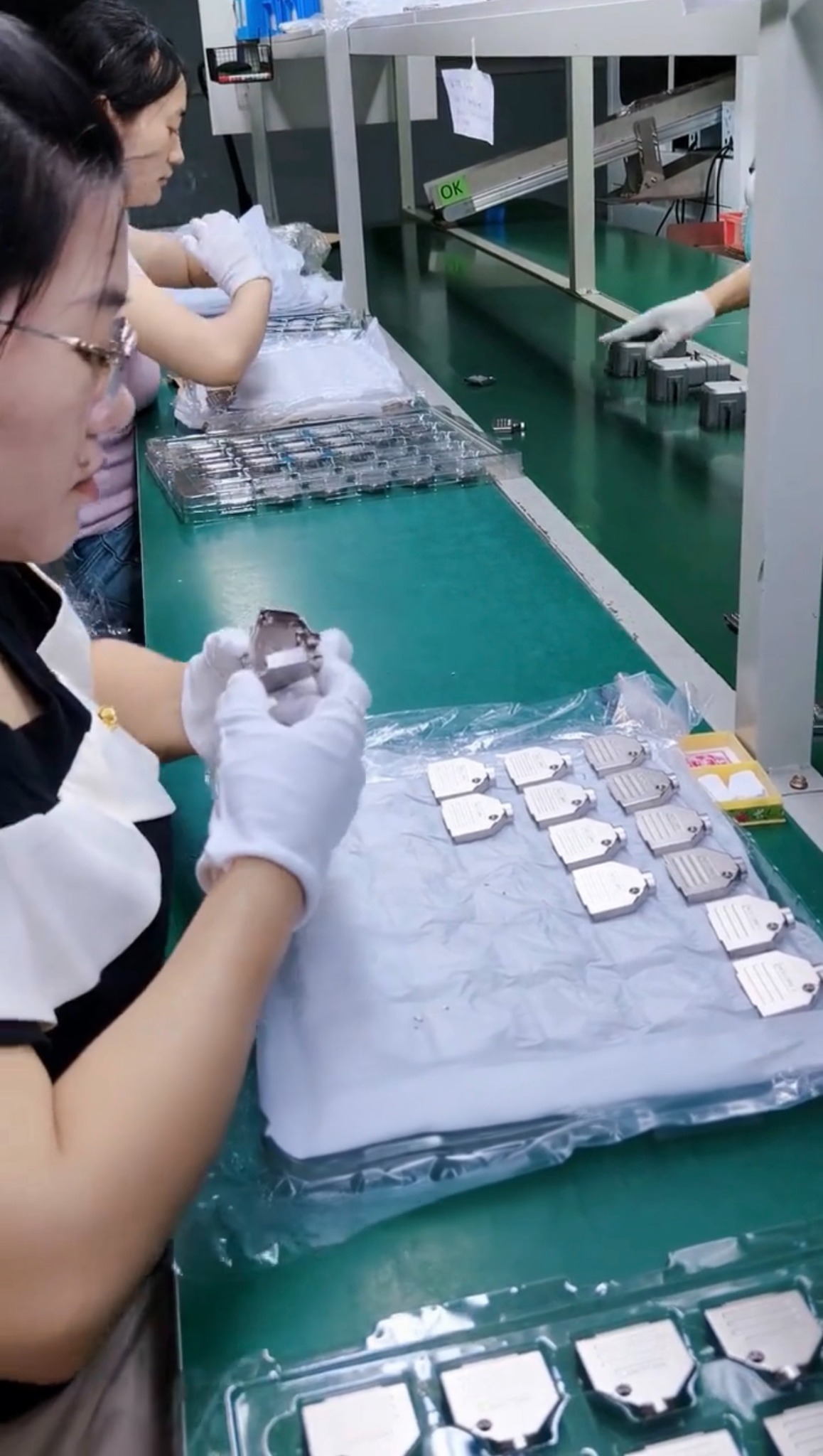
Inspection starts with the drawing, application and acceptance requirements. Samples and production batches have different review priorities. Agree inspection methods, sampling frequency, items requiring individual inspection and report scope before production.
Sample review
Critical dimensions: Check mounting hole spacing and position, mating surface heights and other dimensions that affect assembly. Agree the scope of any full dimensional inspection and report for the project.
Threads: Use suitable thread gauges where required and check effective depth and hole entry condition. Tightening torque or resistance to thread stripping requires a separately agreed verification method.
Assembly: Where customer-supplied or approved mating parts, gauges and assembly conditions are available, check the corresponding fit, alignment and possible interference.
Appearance and finish: Use the agreed appearance criteria or reference samples to assess visible defects, machining marks, color and texture. Internal defect requirements need separate inspection methods and acceptance limits.
After the agreed checks, submit samples and the specified inspection records to the customer. Record any changes in the drawing, sample or inspection documentation, complete the agreed confirmation process, then schedule production.
Production inspection and shipment checks
During production, the agreed inspection plan defines process and shipment checks for critical dimensions, threads, burrs, appearance and finishing. The plan specifies which items are sampled and which are checked individually.
Request batch dimensional reports, special tests or particular records during quotation and production planning so that the method, cost and schedule can be confirmed.
5 Compare quotations and plan delivery
Brackets with similar shapes can have different prices because the tooling, machining, inspection and delivery scope differ. When comparing quotations, first check that the included work and acceptance conditions are equivalent.
Main quotation factors
Tooling complexity: Cavity count, side core pulls, deep recesses and complex features affect toolmaking, trials and maintenance.
Material and production planning: Alloy grade, material used for the part and gating system, batch size and order frequency affect material costs and production planning. Consistent batches can help spread setup costs, but unit prices still depend on the actual operations.
Machining: The number of holes and machined faces, precision requirements, fixture setups and inspection requirements affect secondary-operation costs.
Finish and packing: Coating system, color, masking and appearance criteria change the scope, as do individual separation, protective inserts and pallet requirements.
The quotation should identify what is included in tooling charges, sample charges, part prices, packing and transport. Agree whether tooling is charged separately or amortized into the unit price.
Schedule and shipment arrangements
The schedule needs to account for drawing confirmation, toolmaking, trials and corrections, customer sample review, production casting, secondary operations, finishing and packing. Changes to the geometry or delivery requirements should trigger a review of their effect on cost and timing.
Select packaging according to part weight, surface condition and transport method. Cosmetic and machined surfaces that can be damaged in contact may need separation or protection. Confirm packing format, quantity per carton, identification and accompanying documents before shipment. Distinguish the factory dispatch date from the expected arrival date.
Send HSX your bracket requirements
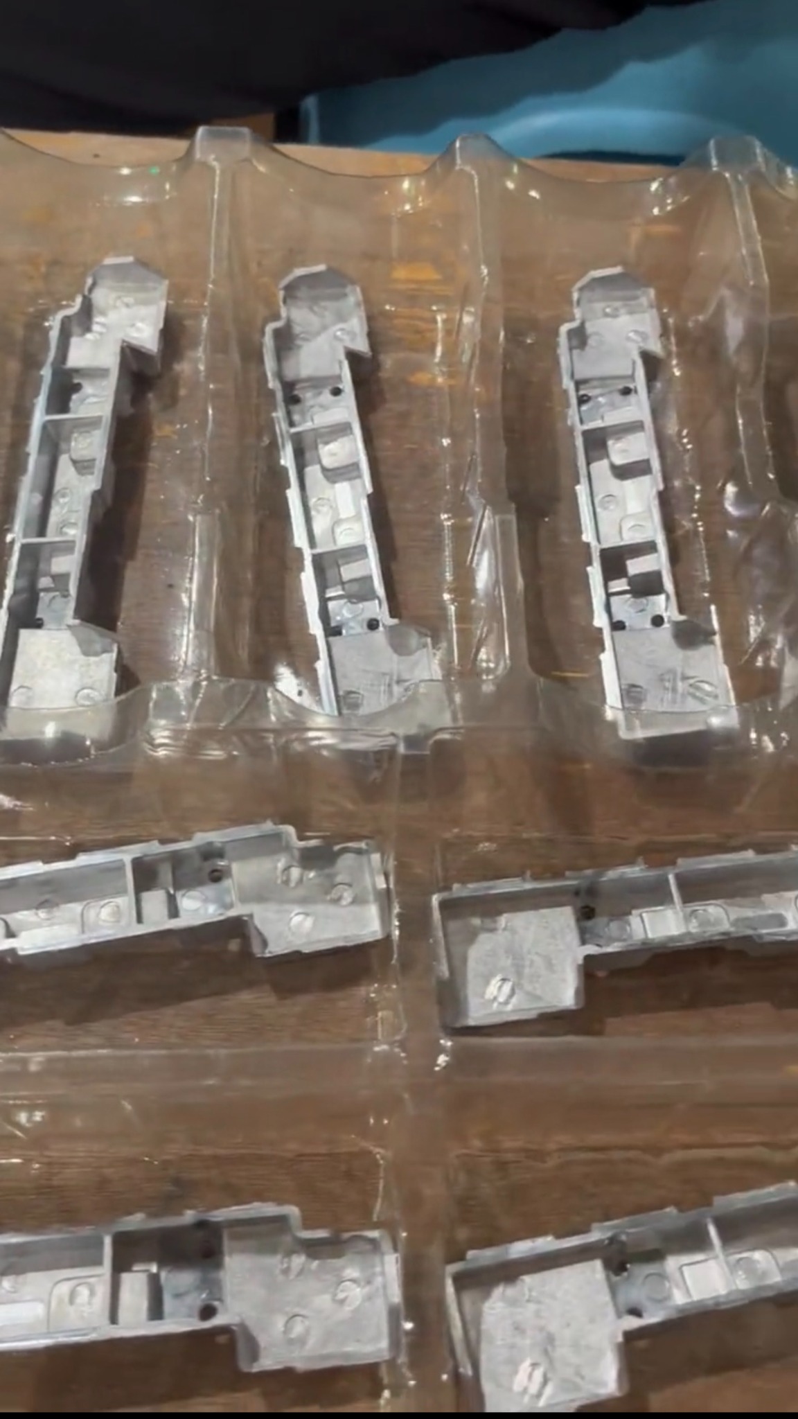
HSX manufactures custom aluminum die cast components to customer drawings, samples and project requirements. We review brackets, supports and mounting components and other parts suited to die casting. In-house operations include die casting, trimming, drilling, tapping, polishing, powder coating, spray painting, quality checks and packing. Required CNC machining and other suitable finishes are coordinated through partners for the project.
For a quotation, provide as much of the following information as possible so that the manufacturing and delivery scope can be defined.
Part information: STEP or STP models, 2D drawings or a physical sample for assessment.
Purchasing plan: Sample quantity, first order, repeat demand and required delivery timing.
Technical requirements: Material, critical dimensions and tolerances, assembly relationships and operating environment.
Delivery requirements: Machining, finishing, inspection reports and packing.
If the information is incomplete, start with the component’s function and the information and files you have available. HSX can identify the missing inputs, assess the manufacturing route and provide a quotation once the technical and delivery scope is defined.
Send your drawing and requirements for project review
Related articles
RFQ Checklist for Custom OEM Aluminum Die Casting Parts
Sandblasting vs Spray Painting vs Powder Coating vs E-Coating
Continue reading
Convert general guidance into a project-specific review.
Share a drawing, 3D file, sample or requirement so HSX can review the actual geometry, process route and finishing boundary.