HSX BLOG
Which Parts of a Die Cast Aluminum Motor Housing Usually Need Machining
See which motor housing features may need machining and what to confirm about fits, faces, threads, machining allowance and inspection datums.
Six design considerations for bores, fits, mounting faces, threads, allowance and datums
A die casting can form much of a motor housing close to its final shape. Machining is then reserved for features whose final size, fit, alignment, seal or fastening function calls for it. The useful question is not how much of the casting can be cut, but which interfaces must meet the controlled drawing after casting.
This article reviews six decisions that engineers and buyers should settle before tooling. The illustrations show possible configurations only. They are conceptual graphics, not customer drawings, process instructions or dimensional specifications.
1 Bearing and shaft interfaces depend on the housing design
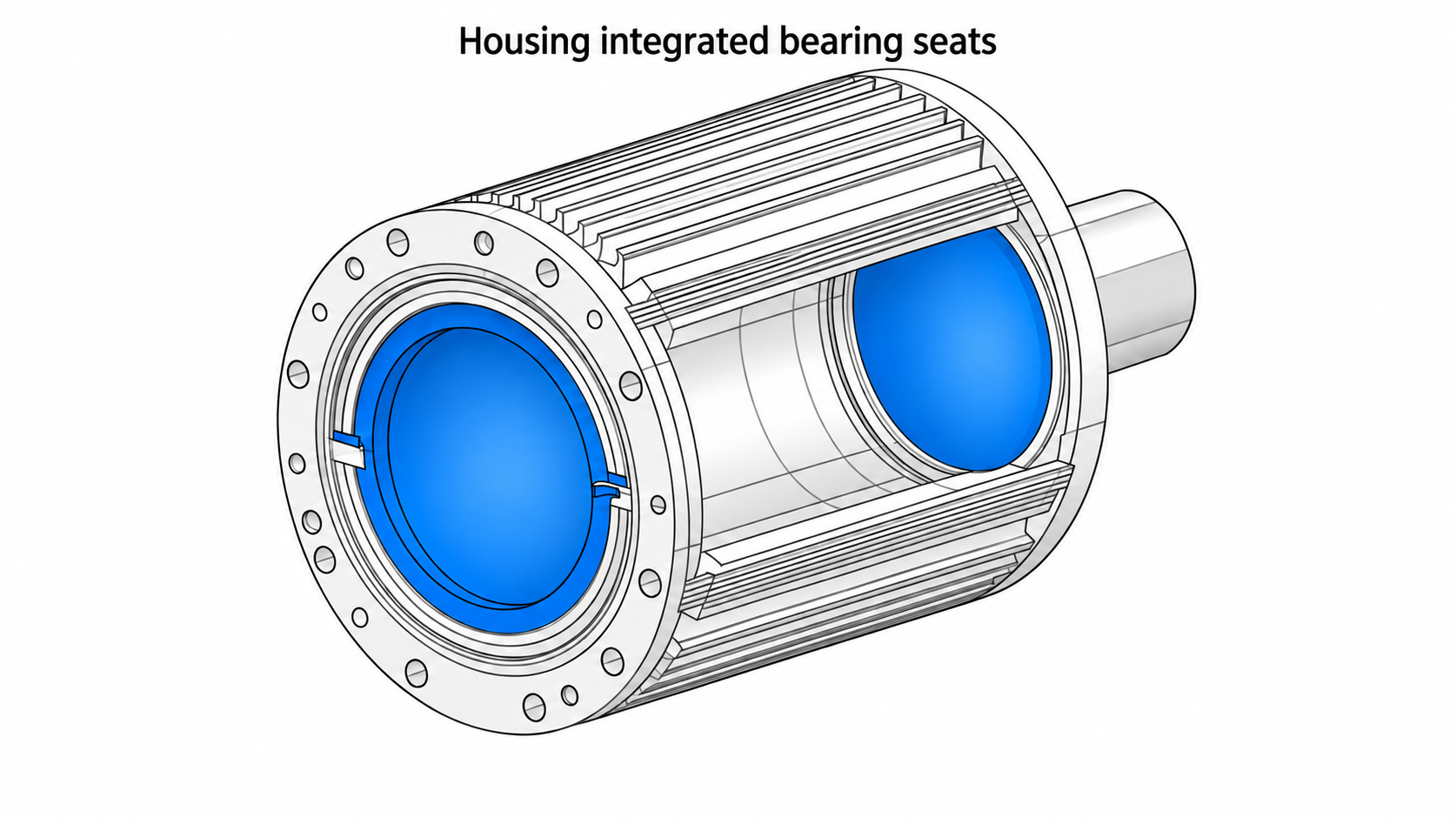
A bearing seat may be in an end cover rather than the main housing. If the housing itself locates a bearing, a shaft seal or another shaft-related interface, that functional bore will usually need a finishing operation. The required diameter, form, surface finish and relationship to mating features should come from the bearing, seal, assembly method and controlled drawing. An as-cast opening can provide a starting shape, but it should not be assumed to provide the finished precision fit.
Where two functional bores must share an axis, the process plan should preserve a common datum relationship. One setup may be appropriate for some parts; other parts may need multiple operations located from the same datums or a dedicated fixture. The choice depends on geometry, equipment access and the specified tolerance.
2 Register fits and stator bores follow the assembly method
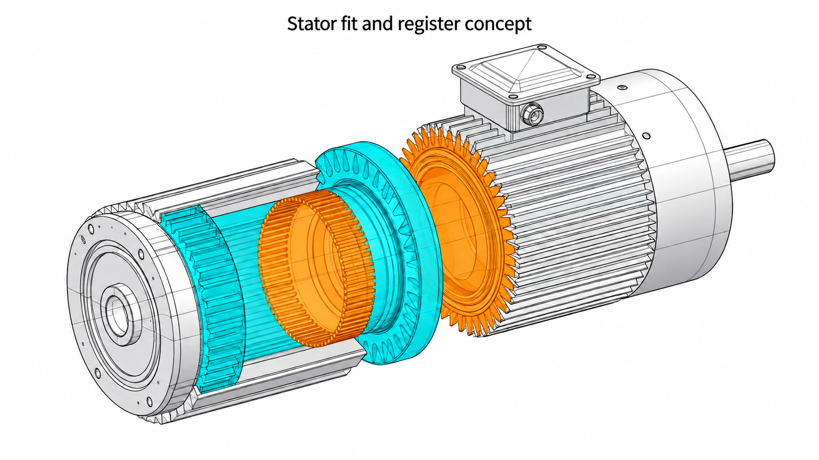
A register between the housing and end cover can establish radial location. If it is a controlled locating fit, the register diameter, mating face and geometric relationship to the relevant axis normally need a defined finishing and inspection plan. Draft on an as-cast surface is one reason the finished fit cannot simply be inferred from nominal casting geometry.
A stator fit bore is another project-specific decision. Further machining may be needed when the stator core relies on the housing bore for positioning, a specified interference fit or thermal contact. Other designs can use a different assembly strategy. Define the machining scope from the stator installation method, fit and thermal requirements rather than from the motor category alone.
3 Mounting and sealing faces depend on what they do
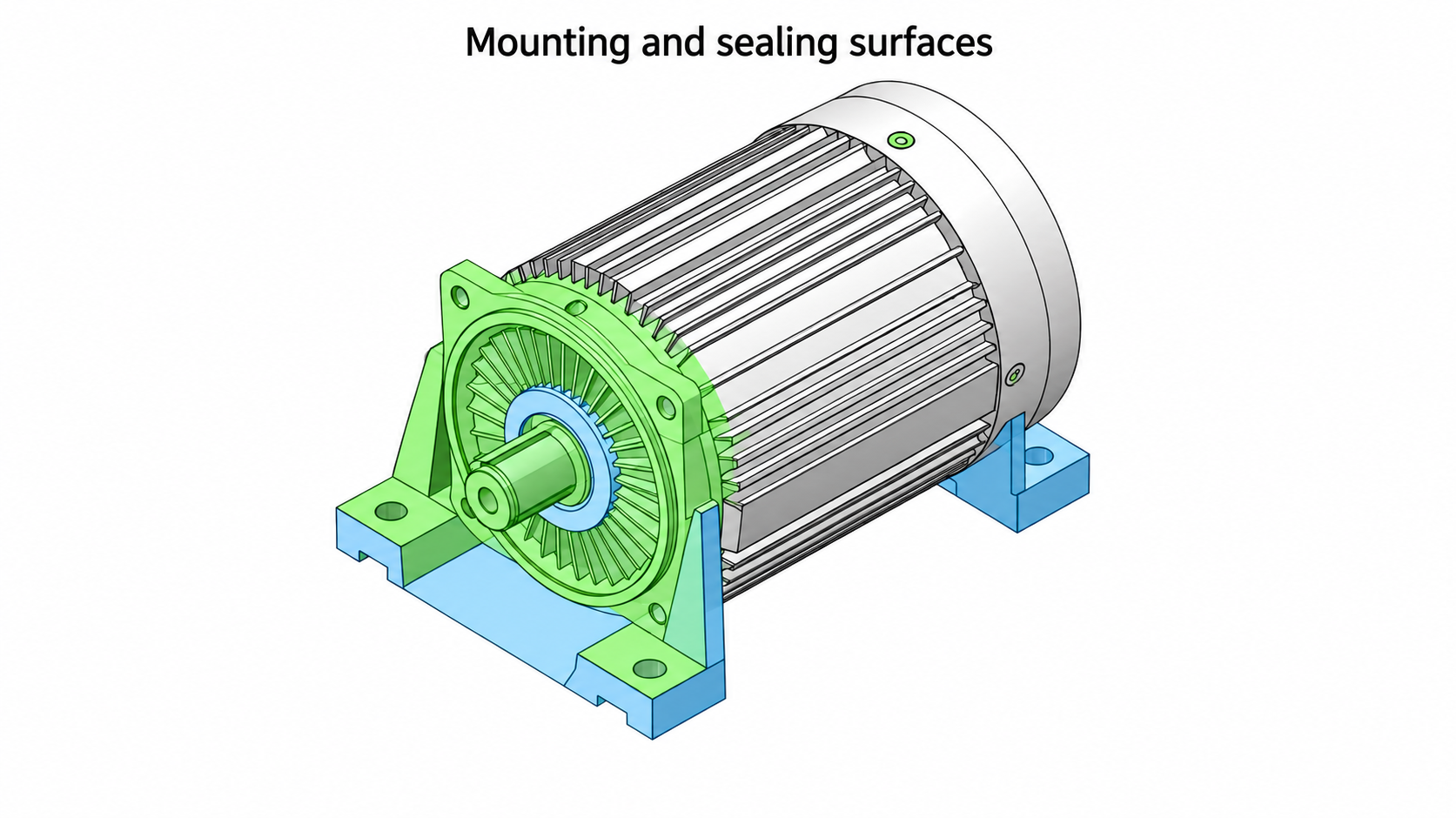
A flange face may locate an end cover, mount the motor to another assembly or participate in a seal. Depending on that function, the drawing may control flatness, surface texture, perpendicularity to an axis, hole locations and the geometry of an O-ring groove. A protection rating by itself does not establish whether a particular face must be machined: the full sealing design, gasket or O-ring, assembly and validation method determine the requirement.
For foot-mounted housings, multiple support pads may need a shared plane to avoid uneven contact during installation. Milling or another suitable finishing method should be evaluated against the mating structure and its drawing. The illustration below shows possible zones; it does not establish an actual seal groove or machining requirement for every part.
4 Threaded holes are usually completed after casting
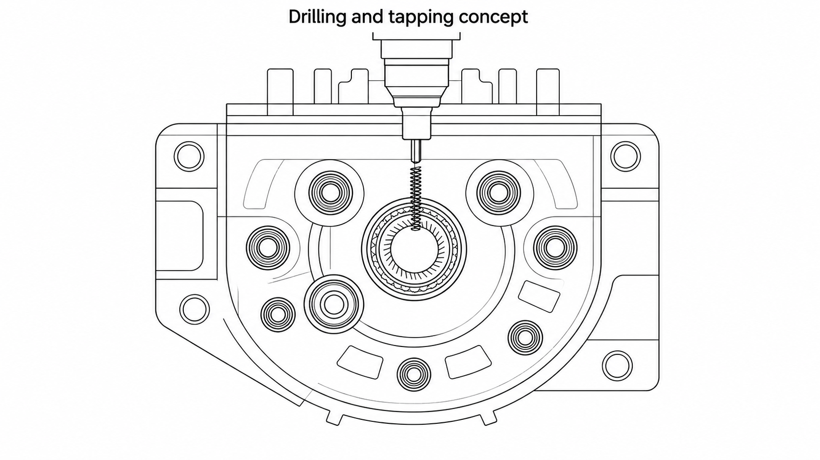
Most internal threads used for assembly are produced after casting by drilling and tapping. Examples include end-cover fasteners, flange connections, terminal-box mounting holes and sensor attachment points. Hole groups that locate a mating part should be controlled against the drawing datums as well as by thread size and depth.
A CNC machine is only one way to perform these operations. Depending on part geometry and volume, drilling and tapping can also be performed on suitable dedicated equipment. HSX performs suitable drilling and tapping in-house; CNC machining is coordinated through partner resources when the project requires it.
5 Machining allowance must balance cleanup and casting integrity
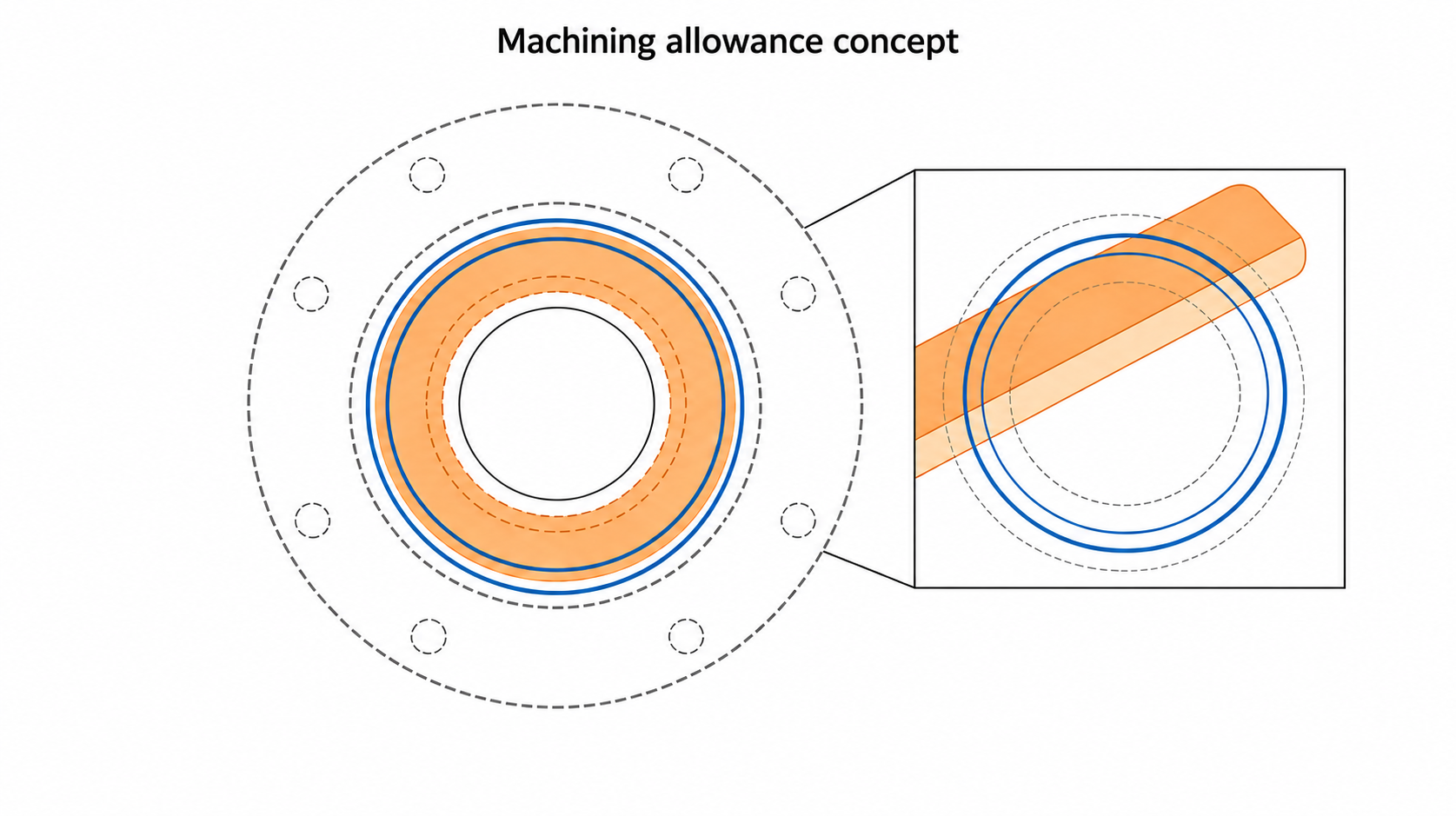
Machining allowance is the material reserved on a casting for later removal. It must account for casting variation, draft, potential distortion, location in the fixture and the final functional surface. Too little allowance can leave portions of the as-cast surface on a specified fit; excessive allowance increases cutting time and material removal.
Deep cutting in a high-pressure die casting can also expose subsurface porosity that was not visible before machining. This is particularly important when a finished area must seal or retain fluid or air. The allowance should therefore be reviewed together with the casting design, sealing strategy, process capability and inspection requirements. There is no universal millimetre range for every motor housing.
6 A consistent datum scheme protects the relationships between features
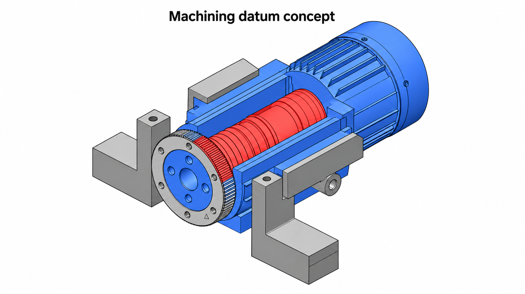
A bore can meet its own size requirement while its position relative to an end face or another bore fails the assembly. That is why the machining and inspection plan must identify which surfaces establish the location of each operation. Related faces, registers, functional bores and hole groups should be evaluated as one datum scheme.
Initial location on the raw casting should use stable regions that are sufficiently rigid and repeatable. Avoid gates, flash, pronounced ejector marks and flexible thin edges as locating contacts. When required, a tooling design can include dedicated locating features. A first machining operation may establish accurate reference faces that later operations and inspection use as finished datums. The exact sequence should be derived from the drawing and fixture plan.
How to define the manufacturing route
Specify the features that actually carry a fit, locate an assembly, form a seal or provide a fastener connection. Then agree on the casting condition, machining datums, final dimensions, inspection basis and the condition in which the part will be supplied. Two housings with similar shapes can have very different machining costs because of their functional features, setup count and acceptance requirements.
For related examples, review HSX’s custom aluminum die cast motor housings, manufacturing capabilities and project process.
Common questions
Does every die cast motor housing need a machined bearing bore
No. A bearing seat may be located in a separate end cover. Machine and inspect a housing bore as a bearing interface when the actual design and drawing assign that function to the housing.
Can an as-cast surface be used for an assembly interface
Sometimes. Whether it is suitable depends on the interface function, casting capability and drawing acceptance criteria. Precision fits, defined sealing faces and controlled datum relationships commonly need further evaluation and may require machining.
How much machining allowance should be added
Set it for the particular feature and manufacturing route. The amount needs to cover casting variation and cleanup without unnecessary cutting or increased risk of exposing porosity, especially at sealing interfaces.
Send your motor housing drawing for project review
Send a STEP or STP model and controlled 2D drawing, if available, with critical fits, datums, seals, alloy, finish and expected quantity. HSX reviews die casting and tooling, confirms in-house steps and coordinates partner CNC machining where needed. Send Your Drawing for Project Review
Continue reading
Convert general guidance into a project-specific review.
Share a drawing, 3D file, sample or requirement so HSX can review the actual geometry, process route and finishing boundary.