HSX BLOG
Die Cast Aluminum Enclosure Design: Holes, Covers and Assembly Interfaces
Designing a die-cast aluminum enclosure involves more than shaping its outer walls. Hole positions, cover joints, sealing features, and mounting interfaces should be reviewed together to reduce tooling complexity, avoid unnecessary machining, and support reliable assembly.
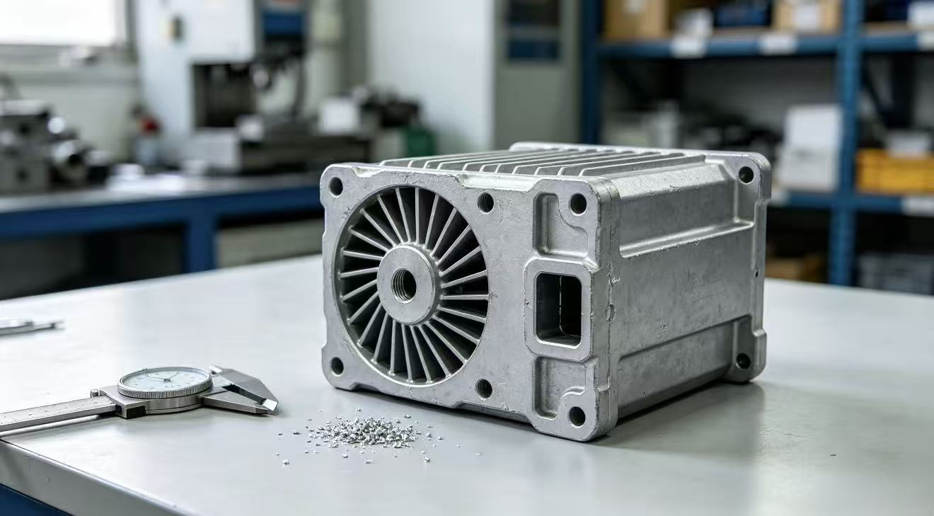
An equipment enclosure drawing may look straightforward: mounting holes, a connector opening, a cover joint and a few screw locations. Yet during die casting review, the team may discover that a side opening calls for a slide core, a screw boss is too heavy at its base, a sealing face cannot meet its flatness requirement as cast, or machining datums do not match assembly datums.
These issues do not necessarily make a part impossible to manufacture. They can, however, change the mold design, trial requirements, secondary machining scope and overall cost. The goal in designing a die-cast aluminum enclosure is not to cast every detail to its final size. It is to establish a sensible division of work between casting, localized machining and final assembly.
This article reviews three important areas: openings, cover joints and assembly interfaces. It also outlines the questions worth answering before a drawing is released for tooling.
1. Hole and Opening Design: Start With the Die-Opening Direction
1.1 Holes aligned with the die-opening direction are often simpler to plan
A hole aligned with the primary die-opening direction may be formed by a fixed core, avoiding additional side-action mechanisms. Whether that is practical still depends on the hole diameter and depth, core support, draft, metal flow and ejection clearance. Long, slender cores may be vulnerable to deflection, wear or misalignment. A single depth-to-diameter rule cannot determine manufacturability for every part.
For relatively large through-holes with modest accuracy requirements, consider whether an as-cast pilot feature is practical. Smaller, deeper or more accurately positioned holes may be better created by leaving solid material or a pilot hole in the casting, followed by drilling, boring or other finishing operations.
1.2 Compare side-action tooling with post-casting machining
A connector window, cable entry or lateral opening does not always need to be produced by a sliding core in the die. If the geometry crosses the main pull direction, the options may include side-action tooling, a different parting arrangement or machining after casting. Side actions add tooling components and maintenance needs; machining adds per-part cycle time, fixturing and location-control costs.
A useful review question is whether the opening must remain an as-cast feature. Then compare its size, annual volume, edge accuracy and location requirements. For a relatively simple window at low volumes, machining may be preferable to a complicated slide mechanism. For a higher-volume, stable design, forming the opening in the die may be more economical. The decision should be made from the actual drawing and cost comparison.
1.3 More vents and narrower grille features are not always better
Closely spaced holes, slots and grilles divide metal flow paths and can require thin die cores. They may increase risks related to incomplete filling, cold shuts, distortion and cleaning. A slot is not automatically easier to die cast than a round hole. Both shapes need to be evaluated against gate location, wall transitions, core stiffness and the pull direction.
For rectangular connector openings, suitable corner radii can reduce sharp-corner stress concentration and support local filling and mold manufacture. If the interface also carries a gasket, dowel or precision connector, mark its final dimensions and functional datums separately. Avoid imposing precision-machined tolerances on every as-cast opening.
1.4 Decide how threaded and locating holes will be finished
Small threaded holes in die castings are often drilled and tapped after casting, with their locations or pilot features provided in the raw casting. Dowel holes, bearing seats and other precisely located interfaces may also need finish machining. For a typical M3 × 0.5 cut thread, a 2.5 mm drill is a common tapping-hole reference, but it should not automatically become the specified die-core diameter. Drill selection depends on the tapping method, alloy and thread requirements.
2. Cover Joint Design: Separate Location, Fastening and Sealing Functions
2.1 A locating lip helps alignment, but does not guarantee a seal
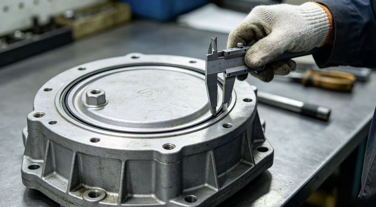
Common equipment-enclosure joints combine a peripheral flange, a locating lip or rabbet, bolted fastening and, where needed, a gasket or sealing ring. A locating feature can help align the cover and body. Its presence alone does not make the joint watertight.
The lip height, clearance, root radii and draft need to reflect enclosure size, assembly method and die pull direction. Where concentricity, flatness or gasket compression matters, the drawing should distinguish features that may remain as cast from critical contact faces that require machining.
2.2 Avoid excessive mass at screw bosses
A screw boss needs enough material for reliable fastening without creating an abrupt heavy section at its root. Localized thickness can lead to uneven cooling and raise the risk of shrinkage porosity or visible sink marks. Simply making a boss thicker does not automatically improve casting quality.
A more balanced approach is to manage wall transitions and, where appropriate, use hollow geometry, ribs and generous root transitions to provide support. The design also needs to account for thread engagement, screw length, tightening loads and available machining access. The final configuration depends on the loading conditions and tooling concept.
For joints that will be opened frequently, threaded inserts or other wear-resistant fastening options may be worth evaluating. Press-fitting a brass insert is not automatically the best choice. Insert material, installation method, interference and the risk of cracking the casting must be checked.
2.3 Design the seal groove around the complete sealing system
For an enclosure requiring resistance to dust or water, first establish the operating environment, intended protection level, seal material, fastening arrangement and maintenance frequency. Groove width and depth, gasket cross-section, compression, corner geometry, surface roughness and mating-face flatness all matter. The task is more than adding a groove around the perimeter.
An as-cast surface may not satisfy the required sealing contact conditions. Critical faces may need a machining allowance, while powder coating or spray painting must be reviewed for possible coating build-up on mating surfaces and changes to gasket compression. Any claimed IP rating must be established through the completed design, assembly and appropriate testing. It cannot be guaranteed from a casting drawing alone.
2.4 Do not make integral flexible snap-fits the default for cast aluminum
A small enclosure may use interlocking details to help position a cover. Features that require significant elastic deformation or repeated opening deserve particular caution. Material behavior, casting defects and fatigue at the root make it risky to copy cantilever snap-fit designs directly from plastic products. Screws, separate spring elements or other mechanical fasteners are often better starting points for enclosures that need frequent access.
3. Assembly Interfaces: Use Consistent Datums to Control Critical Features
3.1 Mounting flanges are about functional contact, not just thickness
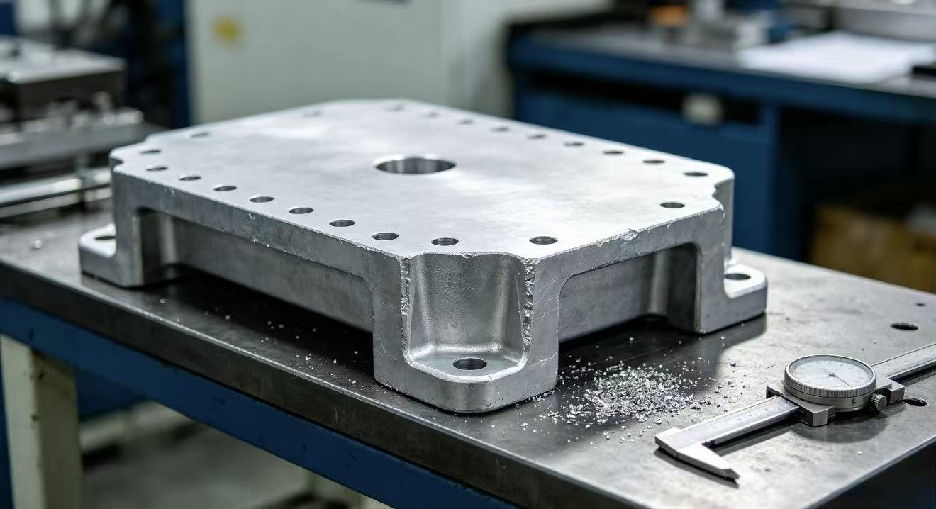
When a flange connects an enclosure to a motor, bracket or machine body, the critical relationships are between the bolt holes, contact face and locating features. Abrupt local thickness changes may contribute to uneven cooling and distortion. If the mounting face has demanding flatness or sealing requirements, assess whether finish machining will be necessary.
Avoid placing uniformly tight tolerances on the entire casting. Instead, identify which positions, surfaces and assembly dimensions really require close control, and agree on appropriate as-cast tolerances for noncritical areas. This helps keep machining and inspection work proportional to the part’s function.
3.2 Mounting feet and lugs must follow the load path
Feet, mounting ears and external bosses may carry bolt preload, vibration or handling loads. Review the available material around holes, rib direction, root radii, wall transitions and die release requirements.
Counterbores are not necessary on every mounting foot. The choice between a counterbore, countersink and plain through-hole depends on the fastener head, tool access and remaining effective wall thickness. When several feet must contact one mounting plane, establish a common datum and decide early whether coplanarity requires machining.
3.3 Review connector geometry, tolerance and coating together
Industrial connectors, cable glands and external fittings normally have their own installation drawings. The design team should supply connector models, required cutouts, fastener specifications and any seals, rather than asking the manufacturer to infer hole positions from a product photograph.
If powder coating or spray painting is specified around these interfaces, identify the holes, threads and mating faces that need masking. Abrasive blasting and other surface preparation steps should not be confused with processes that form a protective coating. Coating thickness and coating boundaries also belong in the assembly review.
3.4 Align machining datums with assembly datums
For example, one end flange may establish the mounting plane, while a nearby locating lip centers the enclosure. If the bore, connector opening and mounting holes all reference those same datums, machining and inspection can follow a more consistent dimensional scheme. If every critical feature is instead referenced to a different as-cast surface, datum changes, repeated setups and accumulated variation can become problems.
For precision features, consider appropriate gripping or locating surfaces that do not interfere with appearance or assembly. Identifying the areas that will require CNC machining during the tooling review can avoid discovering too late that the part is difficult to fixture or locate.
4. Three Design Mistakes That Often Increase Cost
Mistake 1: Expecting every hole to be fully formed in the die
The more economical route may be a die-cast main body with a limited number of critical holes machined afterward. Whether to add a slide or leave machining stock should be decided by comparing mold complexity, per-part machining work and program requirements, rather than aiming for zero secondary machining at all costs.
Mistake 2: Adding mass wherever more strength is needed
Piling material around screw bosses, flange corners or mounting lugs can create unfavorable hot spots. Evaluate load paths, rib layout, wall transitions and metal flow together so that a strength improvement does not introduce a casting-quality problem.
Mistake 3: Applying the same tight tolerance to every dimension
Mounting datums, sealing faces and locating holes may require close control. Non-mating cosmetic surfaces often do not. Failing to distinguish critical from noncritical dimensions increases mold adjustment, machining and inspection work, and may slow down project review.
5. What to Prepare Before Sending an Enclosure Drawing to a Manufacturer
To help a manufacturer assess die casting feasibility more efficiently, provide a dimensioned 2D drawing and preferably a STEP/STP 3D model. Include the following project information:
Part function, installation method and operating conditions, including indoor or outdoor use, temperature, vibration and corrosion exposure.
Preferred alloy or required material properties; if undecided, indicate whether the manufacturer may recommend an option.
Critical mating faces, holes, threads, locating datums and tolerances.
Cover joint method, sealing expectations, connector and fastener specifications, and whether repeated service access is needed.
Surface finishing requirements, including which holes, sealing faces and threads need masking.
Expected quantity, potential repeat orders, target schedule and packing requirements.
With these details, the team can separate features intended to be formed in the mold from in-house operations such as drilling and tapping, as well as identify precision CNC work that may be arranged through partner resources. This also makes the cost discussion more meaningful than a quick price estimate based only on the outside dimensions.
Conclusion: Build Manufacturability Into the First Design Review
A die-cast aluminum enclosure is easier to industrialize when its geometry and manufacturing route are developed together. For openings, compare the die pull direction with machining alternatives. For cover joints, treat location, fastening and sealing as separate design functions. For assembly interfaces, use consistent datums and give critical tolerances the attention they need.
HSX focuses on custom, small- to medium-size OEM aluminum die-casting projects made to customer drawings. Depending on the approved scope, in-house work may include die casting, trimming and deburring, drilling, tapping, polishing, powder coating, spray painting and quality inspection. Precision CNC machining and other specialized processes can be assessed and coordinated through partner resources. Our aim is to identify tooling, machining and assembly issues before a mold is made.
If you are developing a motor-related housing, equipment control enclosure or industrial mounting housing, share your 2D drawing and STEP/STP model together with the expected quantity, critical dimensions and operating environment. Send your drawing for an HSX project review before tooling.
Continue reading
Convert general guidance into a project-specific review.
Share a drawing, 3D file, sample or requirement so HSX can review the actual geometry, process route and finishing boundary.